Beri
Configure simulator
./memoryconfig (or $CHERI_MEMORY_CONFIG), describes how the hardware should be simulated.
Individual simulated hardware periperals are built as shared libraries; The simulator will use dlopen() to load the libraries; Any module specific options are passed to the module at load-time.
C-like syntax in the configuration file.
module statement to load the simulated device module.
device blocks to declare devices by declaring a class.
classselects the simulated device type.- the base address (
addr) and length (length) must be specified; - optional:
irq, class-specific parameters (sockets types, file paths, etc.) - conditionally define device using
ifdefifndef can use
getenvto set options.// configure example module ../../cherilibs/trunk/peripherals/dram.so module ../../cherilibs/trunk/peripherals/ethercap.so module ../../cherilibs/trunk/peripherals/uart.so device "dram0" { class dram; addr 0x0; length 0x40000000; }; ifdef "CHERI_KERNEL" device "kernel" { class dram; addr 0x100000; length 0xff00000; option path getenv "CHERI_KERNEL"; option type "mmap"; option cow "yes"; }; ifdef "CHERI_SDCARD" device "sdcard0" { class sdcard; addr 0x7f008000; length 0x400; option path getenv "CHERI_SDCARD"; option readonly "yes"; }; ifndef "CHERI_CONSOLE_SOCKET" device "uart0" { class uart; addr 0x7f000000; length 0x20; irq 0; option type "stdio"; } ifdef "CHERI_CONSOLE_SOCKET" device "uart0" { class uart; addr 0x7f000000; length 0x20; irq 0; option type "socket"; option path getenv "CHERI_CONSOLE_SOCKET"; }
Simulation
sim: the simulator binary.
mem64.hex: the physical memory image loaded into the simulator; used to populate memory contents for BRAM; the one generated from sw contain a small interactive test suite that communicates via a simulated serial I/O hooked up to the simulator’s standard input and output streams.
To run the simulator, we need a mem64.hex file in the current working directory. Can copy one from a software build such as cheri/trunk/sw or simboot; alternatively, the test target will build the simulator and then run the test suite with suitable options.
Arguments:
+debug: all debug information (debug, debug2, trace)
+xxxx: for use by debug2(“xxxx”, display/actions…)
+trace:
+cTrace:
+regDump:
Testing
TODO: testing infra & result analysis
Before run: build the simulator under cheri/trunk
To run:
- cheritest/trunk: test suite to exercise processor features: initial register values, memory access, jump instruction, exceptions, and so on.
make testin cheritest/trunk will run the test suite
Two categories of tests:
- raw tests.
- exercise basic CPU features such as the register file.
- prefixed 1 with
raw_.
- higher-level tests.
- depends on common CPU initialization code and a support library, such as
memcpy. - prefixed 1 with
test_. - relying on
init.sframework to setup the stack, dump register state on completion, and terminate the simulator.
- depends on common CPU initialization code and a support library, such as
Test structure
- each high level test implement a global
testfunction. - Nose test framework will check the register after
testterminates. - Test framework will change the program counter, $PC, after test returns. No other register changes will be made.
- 1K stack.
- cached, unmapped region: 0x9800,00000,4000,0000 – 0x9800,0000,8000,8000 (stack from here down)
- uncached, unmapped region: 0x9000,0000,4000,0000 – 0x9000,0000,8000,0000 (stack from here down)
- cached, mapped memory regions, and CP0 MMU operations can also be used.
- Each test with 100,000-cycle limit to terminate.
- can catch infinite loops, exception cycles, etc.
- can be changed. ??? where ???
Add new tests
- write Nose test files
- begin with
test_as high-level test - begin with
test_rawas low-level test - add src to
TEST_FILESvar in Makefile; can use subset such asTEST_ALU_FILES - add dir to
TESTDIRSin Makefile
Python Attributes in test
Default no attributes: expected to work on any processor that compiles with mips r4000 isa.
FPGA board Terasic DE4
Building BERI for Synthesis
make verilog COP1=1 ./sim
The BERI verilog build will generate a set of Verilog files in the ip/ directory, with mkTopAxi.v containing the top level module.
Synthesizing BERI for Terasic Board
Terasic directory: cheri/trunk/boards/terasic_de4
build targets:
- all. Build everything except download.
- build_cheri. Builds the BERI processor.
- build_peripherals. Builds the peripherals.
- build_miniboot. Builds miniboot ROM and copy initial.hex here
- build_qsys. Builds Qsys project containing BERI, etc.
- build_fpga. Synthesize, map, fit, analyze timing, and generate FPGA image.
- report_critical. Scans
build_fpgareports for critical warnings - report_error. Scans
build_fpgareports for errors. - download. Attempts to download the FPGA (.sof) image to the FPGA but the chain file (.cdf) may need to be updated for your configuration (e.g. USB port number).
- clean. Removes Quartus and Qsys build files.
- cleanall. clean + clean peripherals, BERI and miniboot.
BERI configuration
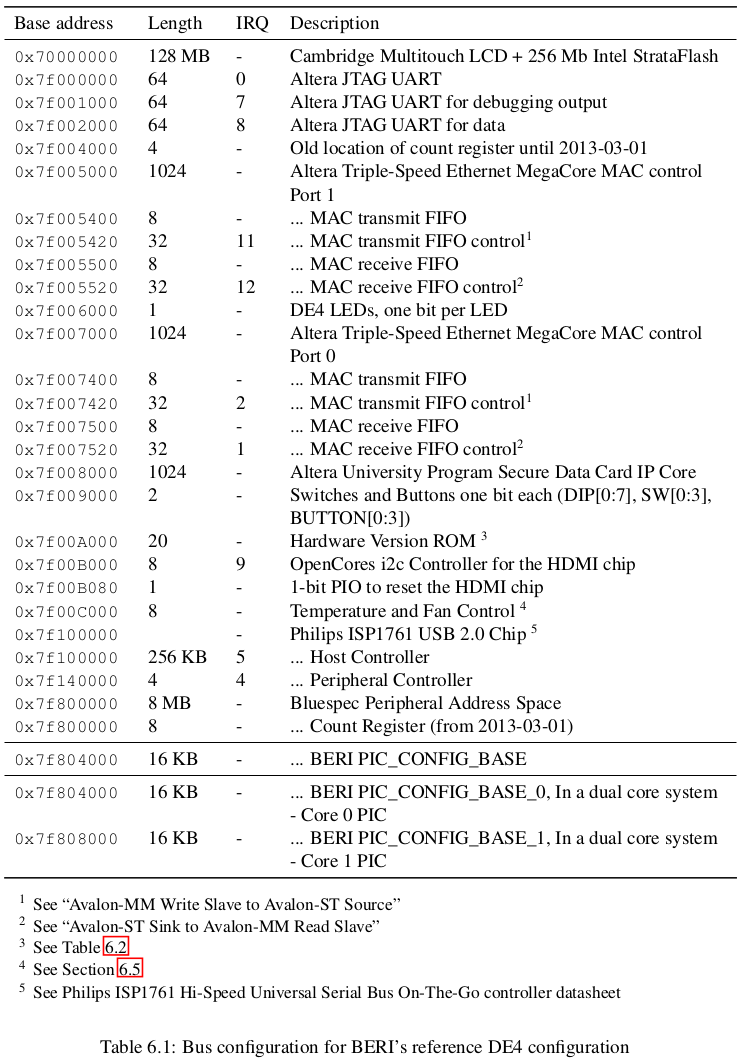
Communication with external I/O devices, such as NICs, is accomplished via a blend of memory mapped I/O, interrupts, and (eventually) DMA.
BERI processor and operating system stack supports a variety of peripherals ranging from Altera “soft” cores, such as the JTAG UART and SD Card IP cores, to “hard” peripherals provided by Terasic on its DE4 development board.
BERI HW refrence (2015 UCAM-CL-TR-868) describes available peripherals and their configuration on the Avalon system-on-chip bus as configured in the BERI reference designs.
Altera IP Cores
BERI and FreeBSD support a number of Altera “soft” IP cores on Terasic tPad and DE4 platforms.
- JTAG UART core
- Avalon-MM and Avalon-ST bus attachments (Embedded Peripherals IP User Guide)
- Altera Triple-Speed MAC (Triple-Speed Ethernet MegaCore Function User Guide)
- SD Card IP core (Altera University Program Secure Data Card IP Core)
Cambridge IP Cores
Two ‘soft’ peripheral devices:
the
countdevice. A memory-mapped register that is incremented on every read(intended for cache testing)soft core for DE4 Multitouch LCD. A memory-mapped interface to the LCD panel, contains support for a pixel frame and a VGA-like text frame buffer suitable for use as a system console.
- Hardware: a parallel interface to drive the LCD + an I2C interface to obtain touhc information.
- (HW) MTL_LCD_Driver: IN - AvalonStream of pixel values; OUT - mapped pixels to the MTL (Multi-touch) LCD color screen (800x480). 24 bits pixel. 33MHz (
mtl_dclk). A dual clock FIFO between this module and the MTL_Framebuffer_Flash. - (HW) MTL_LCD_HDMI: an alternative to the MTL_LCD_Driver. Mirror to HDMI, then to VGA. 720x480; 27MHz. A dual clock FIFO between this module and the MTL_Framebuffer_Flash.
- (HW) MTL_Framebuffer_Flash: provides a memory-mapped frame buffer using the DE4’s off-chip SSRAM to store the frame buffer and provides access to the Flash (which is on the same bus as SSRAM). Provides an Avalon memory-mapped interface that allows a processor to write to the SSRAM. 100MHz.
- (HW) Libraries
- AlteraROM (a font ROM initialized from
fontrom.mif) - VerilogAlteraROM.v (provides Verilog wrapped by AlteraROM)
- Avalon2ClientServer (provides the Avalon memory-mapped interface)
- AvalonStreaming (provides the Avalon streaming interface).
- Software:
- MTL_Framebuffer, 8MB = 0-2MB SSRAM + 4-8MB control registers
mtl_test_small.cis an example which drives the MTL-LCD using a NIOS for some helper functions, and so on.
HDMI Chip Configuration via I2C
- Terasic HDMI_TX_HSMC daughter card on the DE board to obtain output mirroring via an I2C interface
- I2C master interface from OpenCore.
- Wrapped in an Avalon interface(cherilibs/trunk/peripherals/i2c/i2c_avalon.sv, cherilibs/trunk/peripherals/i2c/i2c_rev03.pdf).
Standalone HDMI Output
HDMI_Driver
support multiple resolutions.
Temperature and fan control
two read-only 32-bit registers.
- addr. 0x0 -> last temperature in degrees Centigrade.
- addr. 0x4 -> the power to the fan as a range from 0 to 255.
Peripherals
- Intel StrataFlash 64M NOR flash

Trouble shooting
cheri/trunk/Makefile
Errors to build:
- ./DMV/*.bsv not found; disable it in Makefile.
target sim
sim sim.dtb sim.so: $(BUILD_DIR_SIM)/sim $(BUILD_DIR_SIM)/sim.so $(BUILD_DIR_SIM)/sim.dtb FORCE
	rm -f sim sim.dtb sim.so
	ln -s $(BUILD_DIR_SIM)/sim sim
	ln -s $(BUILD_DIR_SIM)/sim.dtb sim.dtb
	ln -s $(BUILD_DIR_SIM)/sim.so sim.so


$(BUILD_DIR_SIM)/sim $(BUILD_DIR_SIM)/sim.so: $(BSV_FILES) $(PISM_LIB) $(EXTRA_LINK)
	rm -f $(CHERILIBS_DIR)/MEM.bo
	mkdir -p $(BUILD_DIR_SIM)
	CXXFLAGS=-D_GLIBCXX_USE_CXX11_ABI=0 MAKEFLAGS= $(BSC) $(BSC_SIM_FLAGS) $(BSC_SIM_LIBS) -simdir $(BUILD_DIR_SIM) -bdir $(BUILD_DIR_SIM) -u -sim $(BLUESPEC_FLAGS) $(BLUESPEC_SIM_FLAGS)-show-schedule $(SIM_BSV_TOPLEVEL)
	CXXFLAGS=-D_GLIBCXX_USE_CXX11_ABI=0 MAKEFLAGS= $(BSC) $(BSC_SIM_FLAGS) $(BSC_SIM_LIBS) -sim -e $(SIM_TOPLEVEL_MODULE) -simdir $(BUILD_DIR_SIM) -bdir $(BUILD_DIR_SIM) -o $(BUILD_DIR_SIM)/sim $(BUILD_DIR_SIM)/*.ba $(EXTRA_LINK)


$(BUILD_DIR_SIM)/sim.dtb: $(BUILD_DIR_SIM)/sim.dts
	dtc -O dtb -o $@ -b 0 $<
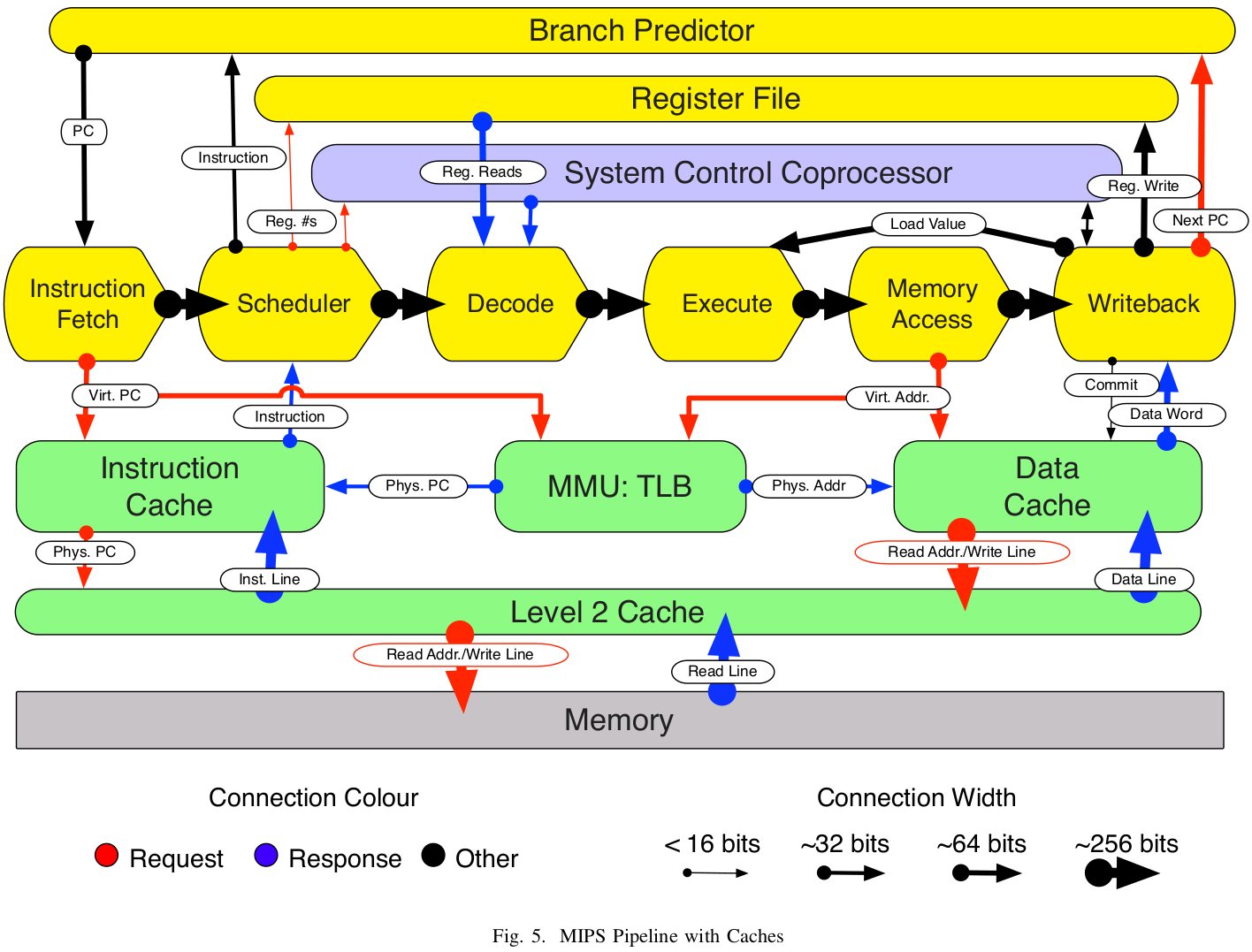
Design overview
BERI (without CHERI extension) pipeline:
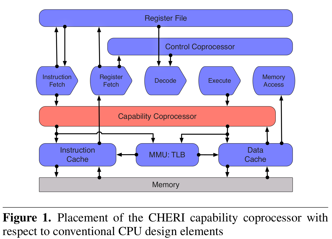
BERI with CHERI coprocessor extension:
2014-isca paper:
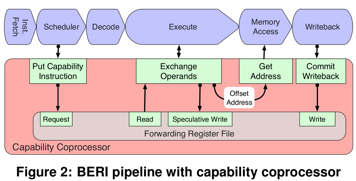
Note: cap coprocessor is tightly coupled with the Execute and Memory Access stages of the pipeline. PCC is validated in the Execute stage to simplify both forwarding and instruction address calculation.
2012-deconflating paper:
Source code overview
In Verilog
TODO
Reference 2
- Piccolo
- Flute
- Beri ISA
- Cheri Source Code reading
Reference 1 reference ↩
Reference 1 reference ↩
Reference 1 Coprocessor 0: system control, MMU Coprocessor 1: FPU. Coprocessor 2: CHERI capability feature. Smaller caches motivated by the performance trade-offs in the FPGA substrate, which provides comparatively high-speed main memory, as well as a desire for simpilicity. Features omitted from MIPS 4000 ISA: only 64-bit, no 32-bit addressing support; only big endian support; no variable-endian features; BERI is usually configured as a single-core, single-threaded processor; Multiprocessor (BERI1) and multithreading (BERI2) are experimental.
TODOs cpu instructions; l2cache; icache; dcache; tagCache; init done; compilation passed. Q&A Memory partitioned in ? see MultiLevelTagLookup.bsv. Possible bugs Bursts is 8 or 4? From TagController.bsv: peekMemResponse: one tagCache response is used for all bursts (frame as index), but the tagCache response only contain tags for 4 flits data’s tags. But somewhere says burst can be up to 8? Does dCache/iCache calls the tag controller?
If you could revise
the fundmental principles of
computer system design
to improve security...
... what would you change?