Logic Verification -- languages
References:
- Electronic Design Automation for IC system Design, Verification, and Testing. By Luciano Lavagno, Igor L. Markov, Grant Martin, and Louis K. Scheffer. 2nd Edition.
Steps of IC design
- design in C/C++ model –> simulators, func good
- design in RTL –> simulating, and compare with the C/C++ reference model
- Synthesis: Translate RTL to gate-level netlist.
- Place and Route: netlist as input, generates polygons that will become wires and transistors on the chip.
Verification: making sure that C and RTL models are functionally correct.
This is the most serious, time-consuming challenge in digital hardware design.
The so-called formal verification techniques, which amount to efficient exhaustive simulation, have been gaining ground, but suffer from capacity problems.
Testing:
- provides no guarantees of completeness, meaning bugs may go unnoticed.
- Good assertions in hardware systems (which often check a temporal property, such as “acknowledge arrives within three cycles of every request”) are much more difficult to write than those for software (which most often check data structure consistency).
- There is no way to know when enough assertions have been added;
- It is possible that the assertions themselves have flaws (e.g., they let bugs by)
- Finally, test cases that achieve 100% coverage can also let bugs by because the criterion for coverage is necessarily weak.
- Coverage typically checks what states particular variables have been in, but it cannot consider all combination because their number grows exponentially quickly with design size.
- As a result, certain important combination may not be checked even though coverage checks report “complete coverage”.
Pure formal techniques
- consider all the possible behaviors by definition;
- do not require explicit test cases (implicitly, they consider all possible test cases);
- do not need to consider coverage;
- But knowing what behavior is unwanted is crucial for formal techniques, whose purpose is to either expose unwanted behavior or formally prove it cannot occur.
History: CTL/LTL based languages
- 1970s[20], Pnueli suggested the use of temporal logic;
early 1980s, research on automatic verification
- linear temporal logic
- computational tree logic
- CCS,
- dynamic logic,
- temporal logic of actions(TLA)
In early 2000s, a sort of renaissance occurred in verification languages.
- Temporal logics, specifically linear temporal logic (LTL), and computation tree logic (CTL):
- form the mathematical basis for most assertion checking.
CTL: specify both liveness properties and safety properties;
- Liveness property: “this good thing will eventually happen”
- Safety properties: “this bad thing will never happen”
LTL: a subset of CTL, expresses only safety properties
- can be turned into checking automata meant to be run in concert with a simulation to look for unwanted behavior.
but their traditional mathematical syntax is awkward for hardware designers.
Instead, a number of more traditional computer languages, which combine a more human-readable syntax for the bare logic with a lot of “syntactic sugar” for more naturally expressing common properties, were proposed for expressing properties in these logics.
Two industrial efforts from Intel (
ForSpec) and IBM (Sugar) emerged as the most complete;- They were later adopted in part by SystemVerilog and VHDL.
CBVfrom MotorolaSome EDA companies were producing languages designed for writing test benches and checking simulation coverage.
Veraandeare two most commercially successful;Vera: originally designed by System Science and since acquired by Synopsys;e: designed and sold by Cadence (formerly Verisity)
==> These industrial languages were donated to the Accellera standards body and have been the basis for defining a new IEEE standard called PSL.
PSL: Property specification language (EDA standard)
- evovled from Sugar language;
- adopted as an IEEE standard (1850-2010);
- grafted onto both SystemVerilog and VHDL;
- act as an add-on to SystemVerilog/VHDL;
- Based on CTL/LTL;
- PSL is divided into four layers:
- Boolean layer (lowest layer), consists of instantaneous boolean expressions on signals in the design under test;
- The syntax of this layer follows that of the HDL to which PSL is being applied;
- Can be verilog, SystemVerilog, VHDL, or others;
- e.g.
a[0:3] & b[0:3]anda(0 to 3) and b(0 to 3)represent the bitwiseandof the four most significant bits of vectorsaandbin the Verilog and VHDL flavors, respectively.
- Temporal layer (second layer), allows a designer to state properties that hold across multiple clock cycles.
- e.g.
always !(ena & enb)states that the signalsenaandenbwill never betruesimultaneously in any clock cycle.- The
alwaysoperator, which states that a Boolean expression holds in every clock cycle, is one of the most basic.
- The
- e.g.
always(req -> next ack)states that in every cycle that thereqsignal is true, theacksignal is true in the next cycle.- The
nextoperator, one of the operators that specify delays.
- The
- e.g.
req -> next[2] ackmeans thatackmust be true two cycles after each cycle in whichreqis true.- The
->symbol denotes implication, that is, if the expression to the left is true, that on the right must also be true.
- The
- e.g.
always {req; ack; !cancel}is a syntactic sugar foralways (req -> next (ack -> next !cancel)), means thatackmust be true after any cycle in whichreqis true, andcancelmust be false in the cycle after that. weakandstrongproperty:weakproperty can be checked in simulation; i.e., for safety properties;strongproperty: can only be checked formally; express liveness properties;- strong property is marked with a trailing exclamation point
!. - some operators come in both strong and weak varieties.
- e.g.
always (req -> eventually! ack)states that afterreqis asserted,ackwill always be asserted eventually. eventually!operator illustrates the meaning of strong operators.- This is not something that can be checked in simulation: if a particular simulation saw
reqbut did not seeack, it would be incorrect to report that this property failed because running that particular simulation longer might have producedack. - This is the fundamental differences between safety and liveness properties: safety states something bad never happens; liveness states something good eventually happens;
- Specify a property in which times moves backward.
always ((a && next[3] (b)) -> c), states that whenais true andbis true three clock cycles later,cis true in the first cycle whenais true.
- Verification layer (third layer), instructs a verification tool what tests to perform on a particular design;
- It amounts to a binding between properties defined with expressions from the Boolean and temporal layer, and modules in the design under test.
The following example declares a “verification unit” called
ex1a, binds it to the instance namedtop_block_i1_i2in the design under test, and declares (the assertion namedA1) that the signalsenaandenbin that instance are never true simultaneously.vunit ex1a(top_block.i1.i2){ A1: assert never (ena && enb); }use directives
assert,assume, assume a given property;assume_guarantee, both assumes and tests a particular property;restrict, constraints the tool to only consider inputs that have a given property;cover, asks the tool to check whether a certain property was ever observed;fairness, which instructs the tool to only consider paths in which the given property occurs infinitely often, for example, only when the system does not wait indefinitely.
Modeling layer (fourth layer): allows Verilog, SystemVerilog, VHDL, or other code to be included inline in a PSL specification.
The intention here is to allow addition details about the system under test to be included in the PSL source file.
The “e” language
- developed by Verisity as part of its Specman product as a tool for efficiently writing test benches.
- an imperative object-oriented language, with following features:
- concurrency,
- the ability to generate constrained random values,
- mechanisms for checking functional (variable value) coverage,
- a way to check temporal properties (assertions).
- Syntax of “e”:
- all code must be enclosed in
<'and'>symbols; otherwise it will be comments; - declarations are written in “name: type.”
- fields in compound types (e.g., structs) includes particles such as
%and!.%indicate when a field is to be driven on the device under test;!indicates when a field is not randomly computed.
- all code must be enclosed in
SystemVerilog
- 1983-1984, Verilog HDL; buoyed largely by the speed of its “XL” gate-level simulation algorithm;
- 1995, IEEE standard;
- 1999, Superlog, a Verilog dialect, extended with software-like constructs; adopted in Verilog standardization body in 2002;
- 1995, Vera language, for describing Verilog test benches; 1998 bought by Synopsys; 2001 OpenVera by Synopsys;
- 2005, Verilog, Superlog, OpenVera were merged to produce the SystemVerilog standard;
One of the SystemVerilog’s strengths remains its ability to represent test benches along with the model being tested;
The following example: a test bench for a simple multiplexier
mux. It applies a sequence of inputs over time and prints a report of the observed behavior.module testbench; logic a, b, sel, f; mux dut(f, a, b, sel); initial begin $display(“a,b,sel -> f”); $monitor($time,, “%b%b%b -> ”, a, b, sel, f); a = 0; b = 0; sel = 0; #10 a = 1; #10 sel = 1; #10 b = 1; #10 a = 0; #10 sel = 0; #10 b = 0; end endmodulethe output of the example:
a,b,sel -> f
0 000 -> 0
10 100 -> 1
20 101 -> 0
30 111 -> 1
40 011 -> 1
50 010 -> 0
60 000 -> 0
Random test generation taken from Vera language;
Coverage constructs;
Temporal assertions; allow a test engineer to specify both desirable and undesirable properties that take place over one, two, or more clock cycles;
- originally from the formal verification community;
- but only for a system when is being subjected to random test vectors;
Verilog Shortcommings:
- Compared to VHDL: SystemVerilog does a poor job at protecting users from themselves.
- Verilog’s variables are shared variables and the language permits all the standard pitfalls associated with them;
- such as races and nondeterministic behavior;
- SystemVerilog allows more dangerous usage;
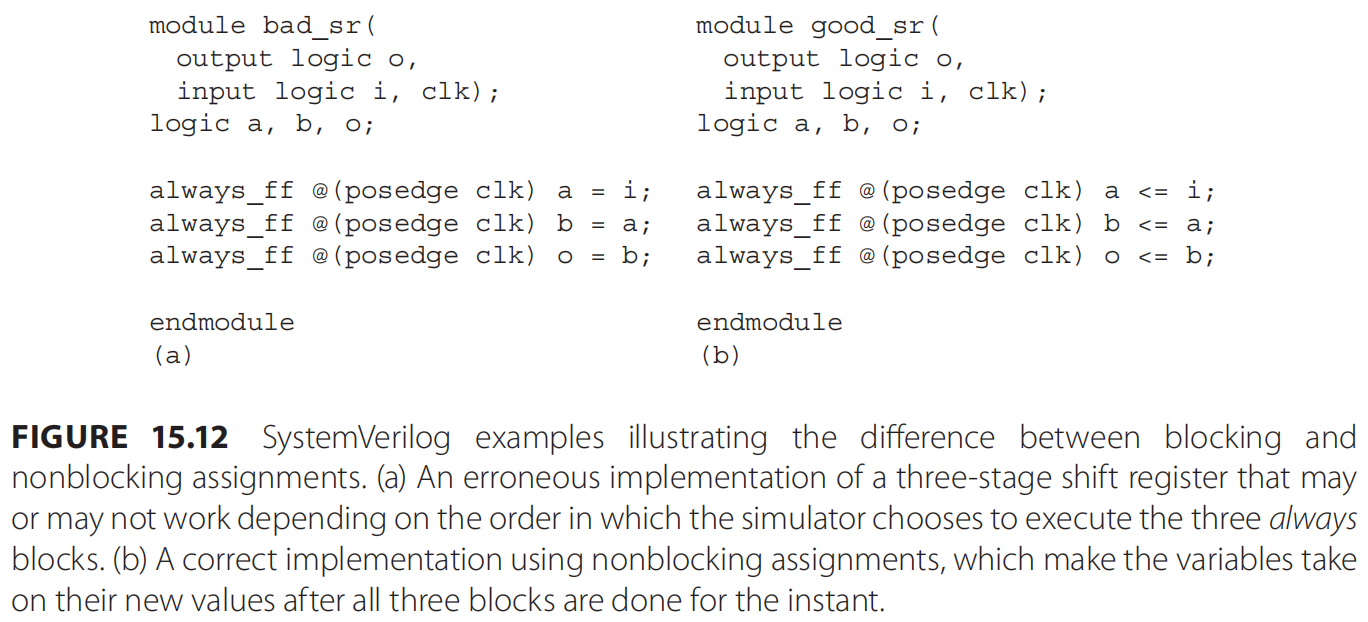
The implementation in Figure 15.12a appears to be correct, but in fact may not behave as expected because the language says the simulator is free to execute the three always blocks in any order when they are triggered.
If the processes execute top to bottom, the module becomes a one-stage shift register, but if they execute bottom to top, the behavior is as intended.
The real danger here is that the simulation might work as desired but the synthesized circuit may behave differently, defeating the value of the simulation.
Figure 15.12b shows a correct implementation of the shift register that uses nonblocking assignments to avoid this problem. The semantics of these assignments are such that the value on the right-hand side of the assignment is captured when the statement runs, but the the actual assignment of values is only done at the “end” of each instant in time, that is, after all three blocks have finished executing. As a result, the order in which the three assignments are executed does not matter, and therefore the code always behaves like a three-stage shift register.
Non-blocking assignments. ???
VHDL
- Created in 1983 and 1984, essentially concurrently with Verilog;
- IEEE standard 1076 in 1987, revised in 1993,2002, 2008;
- The orignal objectives of the VHDL language were to provide a means of documenting hardware (i.e., as an alternative to imprecise English descriptions) and verifying it through simulation. As such, a VHDL simulator was developed along with the language.
- A verbose syntax derived from Ada;
- Like SystemVerilog, VHDL describes designs as a collection of hierarchical modules;
- Unlike SystemVerilog, VHDL splits modules into syntactically into two parts:
- interfaces: called entities, and
- their implementations, called architectures;
- Case Insensitive;
BitandBITare equivalent;
Verification in VHDL
Assertions;
can be used to check temporal properties;
process begin
wait until clk'event and clk = '1' and request = '1';
wait until clk'event and clk = '1';
assert acknowledge = '1';
end process;
support PSL constructs:
assert always (request -> next acknowledge);
SystemC
“The few commercial products that have provided hardware synthesis from SystemC have met with little commercial success”.
Much faster for higher-level models than Verilog/HDL;
On detailed models, the simulation speed of a good compiled-code Verilog or VHDL simulator may be better;
- the contex-switching cost in SystemC is higher than that of a good Verilog/VHDL simulator when running a more detailed model;
- a system with many small processes would not simulate as quickly;
More
If you could revise
the fundmental principles of
computer system design
to improve security...
... what would you change?